(a) The graph below shows that peak voltage doubles but frequency remains the same if the field strength doubles.
(b) The graph below shows that both frequency and peak voltage doubles if the rate of rotation doubles.
My thanks to Peter Finch from St Joseph's College, Gregory Terrace, for these (pdf) solutions.
The rest are from Glenn Rossiter:
Q3 :-Square coil positioned within field of B = 150 x 10-3 T. It has side AB = 5.0 cm which is length(L) in the induction formula EMF = B.L.v
If coil moves at v = 8.5 m.s-1.
(a) Voltage across AB = VAB = 0V.
Voltage across DC = 0V.
Voltage across AD = VAD = B.L.v = 150 x 10-3 x 5 x 10-2 x 8.5 = 0.06V, which is also voltage across BC.
(b) No current will flow as voltage across AD opposes voltage across BC.
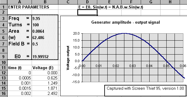
Given B = 0.15 T, Area A = 0.02 m2 and turns N = 150. Coil rotates at f = 50 Hz.
Using the Peak output voltage E0 = N.A.B.w = N.A.B 2pf = 140 volts.
An alternative to this answer is to use an Excel spreadsheet that automatically calculates the required values and plots them as would an oscilloscope instrument.
The screen shot below illustrates such a spreadsheet using "absolute reference cells" to calculate the generator output voltage for this question. Notice that the Peak voltage is 141.3 volts :-
This type of spreadsheet is "active" and both table data and chart display will update as new values are entered into the parameter box at upper left :-
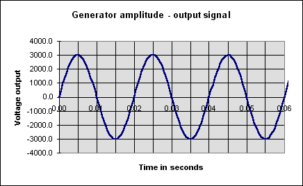
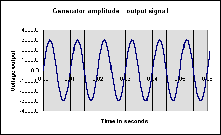
In answering this question the same Excel spreadsheet as Q10 is used and by comparison to the plot given
(a) The graph below shows that peak voltage doubles but frequency remains the same if the field strength doubles.
(b) The graph below shows that both frequency and peak voltage doubles if the rate of rotation doubles.
Given Galvanometer resistance Rg = 5W, and N = 200 turns with an Area of 50 cm2, and total coil resistance Rc = 20W
Change in the field strength DB = (30 - 20) mT = 20 mT, over a time interval Dt = 0.02 s.
Thus the EMF = N.DB.DA/Dt which yields a value of 1.0 V.
Using Ohm's law the circuit current = V/R = 0.04 A = 40.0 mA.
The hospital generator produces 40 kW at 250 VAC with total distribution resistance = 0.2W.
Using P = V.I yields I = 40kW/250V = 160 A.
(a) Power loss = I2.R = (160)2. 0.2 = 5.1 kW.
(b) Voltage loss = I.R = 32 V. Thus voltage at hospital = 218 V, which would not be satisfactory for appliance use.
(c) The voltage drop would be even more considerable.
(d) At 10 kV, I = 40 kW/10 kV = 4A, with subsequent power loss = 32 W and a voltage loss = I.R = 4 x 0.2 = 0.8 V. Assuming perfect transformers. This situation is obviously much more ideal for the hospital electrical supply.
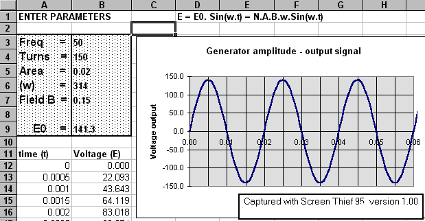
Again using the active Excel spreadsheet or by substitution into the output voltage formula a frequency of 10 Hz is found. The screen shot below indicates the appropriate settings :-